updated 10-30-2014
Tesla’s Flying Stove
“The Tesla Space Drive”
Fuel-Efficient Propulsion Systems for Spaceships
* “Not the airplane, the flying machine,” responded Dr. Tesla. *
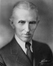
“I am now planning aerial machines devoid of sustaining planes, ailerons, propellers, and other external attachments, which will be capable of immense speeds” – Tesla’s autobiography
“To a Westinghouse manager, Tesla wrote ‘You should not be at all surprised, if some day you see me fly from New York to Colorado Springs in a contrivance which will resemble a gas stove and weigh as much. … and could, if necessary enter and depart through a window.'” (7-7-1912)
[ it will be a small box, not a huge “cigar” ]
pg. 198 Tesla: Man Out of Time by Margaret Cheney
Tesla intended the world to have a free, wireless, source of power “My power generator will be of the simplest kind — just a big mass of steel, copper and aluminum comprising a stationary and rotating part, peculiarly assembled.”
According to museum officials at The Nikola Tesla museum in Belgrade, “he left sketches of interplanetary ships. This information, however, has not been made available to western scholars.” pg. 203
After these experiments I planned to build a flying machine, which could fly not only in the air but within interplanetary space.
The principle of operation of the flying machine is as follows: towards the flight direction, compression of the ether is to become weaker by the generator installed in the flying machine. As the ether keeps pressing with prior intensity from all other sides, then the flying machine began moving. Being within this flying machine you will not feel its speeding-up as the ether is not to hamper your movement. I had to abandon my plans to create the flying machine. There were two reasons for it: first, I have no money to work in secret. But the main reason is that the great war began in Europe and I wouldn’t like my inventions used to kill! When on earth will these madmen stop?
see our page “Tesla’s Unk. Manuscript”
How Tesla intended to power his flying machine
“The flying machine of the future — my flying machine — will be heavier than air, but it will not be an airplane. It will have no wings. It will be substantial, solid, stable.
You cannot have a stable airplane. The gyroscope can never be successfully applied to the airplane, for it would give a stability that would result in the machine being torn to pieces by the wind, just as the unprotected airplane on the ground is torn to pieces by a high wind. My flying machine will have neither wings nor propellers. You might see it on the ground and you would never guess that it was a flying machine. Yet it will be able to move at will through the air in any direction with perfect safety, at higher speeds than have yet been reached, regardless of weather and oblivious of ‘holes in the air’ or downward currents. It will ascend in such currents if desired. It can remain absolutely stationary in the air even in a wind for great length of time. Its lifting power will not depend upon any such delicate devices as the bird has to employ, but upon positive mechanical action.” [Here it is again: “mechanical”]
“You will get stability through gyroscopes?” I asked. ” Through gyroscopic action of my engine,* assisted by some devices I am not yet prepared to talk about,” he replied.
* [notice that ‘eccentrics’ G,H,J, & K in the drawing below, DO throw their weight around in a “gyroscopic action”, like spinning tops. The “device” could be the orientation of the 4 objects which generates an unprecedented, physical law breaking, 5th spin, 5th orbit, without the centripetal force physically needed to hold it there.]
Science: “The ability of a gyroscope to ‘defy gravity’ is baffling.” and “When a force is applied to try to rotate the spin axis of a gyroscope, the gyroscope reacts to the input force along an axis perpendicular to the input force” “according to the right-hand rule”. This is called “gyroscopic precession”.
Dr. Tesla smiled an inscrutable smile. “All I have to say on that point is that my airship will have neither gas bag, wings nor propellers,” he said. “It is the child of my dreams, the product of years of intense and painful toil and research. I am not going to talk about it any further. But whatever my airship may be, here at least is an engine that will do things that no other engine ever has done, and that is something tangible.”
from the book Tesla’s Engine — A New Dimension For Power
Tesla had contracted with both Allis Chalmers and with Westinghouse’s railway and lighting division to build a 36,000 rpm turbine to “fly from New York to Colorado Springs in a contrivance which will resemble a gas stove” – July 7th 1912.
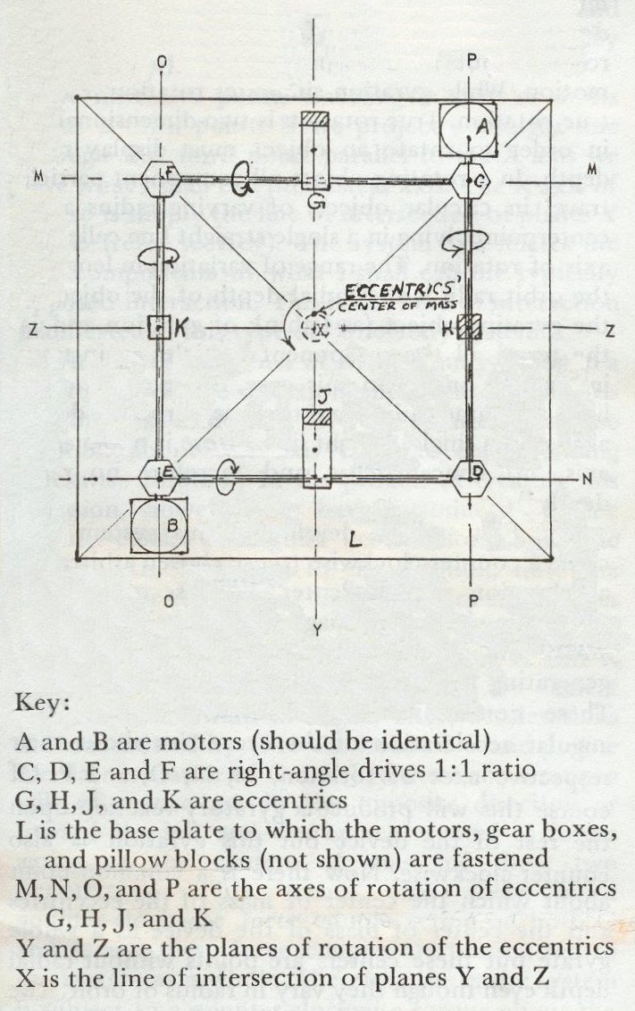
Tesla, Man of Mystery is a book that has, along with general info. on Tesla and a few fables, one diagram and enough information about it, amid the theories, posturizing, and misinformation – for us to duplicate the device.
Chapter 4 is titled the “Tesla Space Drive” and it appears to be the heart of what Tesla had said would look like flying on “a gas stove” and be “peculiarly assembled.” (above)
So, here it is:
Tesla, Man of Mystery
chapter 4
The Tesla Space Drive
for interplanetary space vehicles
The Flying Stove – Flying Machine
The Force Field Generator
page 31
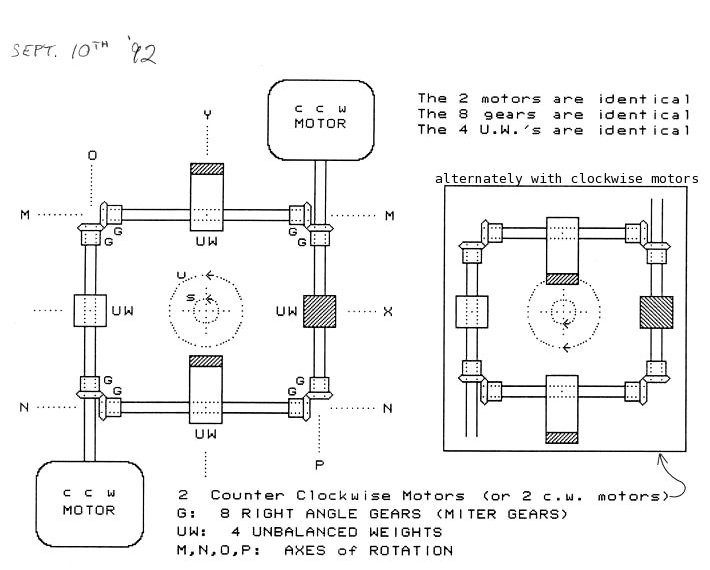
Diagram from page 31 of Tesla, Man of Mystery © 1992
Chapter 4: “The Tesla Space Drive”
“The first step in developing this system is to cause a counter-clockwise (sense chosen arbitrarily) acceleration of the center of mass of the four eccentrics (refer to diagram) in a circular orbit about the X axis.
“… there is a common point about which the center of mass of the eccentrics and the center of mass of the device as a whole gyrate.” pg.32
“The reaction to this angular acceleration is a linear acceleration along the system axis (X) and directed outward from the page. … this system functions in accordance with the right-hand rule. … [ It will ] “wobble noticeably at low thrust levels. This effect fades out, however, as the thrust is increased.” pg.34-35
Unbalanced Forces
No one can “see” a centripetal, horizontal, force when a wire is wrapped into a circular coil and laid FLAT on a table. If the coil is horizontal, the electricity and the electrons are traveling horizontally. There may be no magnet in the center to hold the electrons in orbit, the centripetal force to hold the electrons in the coil. Next, if everything is in balance, where does any vertical force come from? And, the wire, the coil, is still NOT moving. It is just sitting there. Would it help to spin the coil?
Without explanation, it is none-the-less true, that electrons are accelerating around, in the coil, with no centripetal force present, and an iron or steel rod in the center of an electrified coil, with enough voltage and current, will be accelerated out at a right angle to the plane of the coil, – according to the left-hand rule.
2. With this “peculiarly assembled” frame, Tesla has created acceleration in a circle with no centripetal force present, and with enough mass and speed (with the lighter the mass of and the higher the speed of the “eccentrics”), the accelerating object, will be accelerated at a right angle to the plane of its orbit, “in accordance with the right-hand rule.”
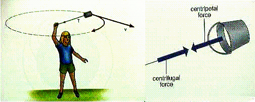
There is no bolt, no string, nothing, providing centripetal force to keep the entire frame in its orbit.
The object, frame, is not spinning, like a coil does not spin, nor do any one of the spinning weights match the orbit of the frame and yet, the center of mass of the object is spinning, in orbit, generating a force according to the right-hand rule 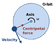 – if the object is centered around the 4 spinning weights. Like electrons in orbit in a stationary coil – an area in which Tesla is already famous – instead of acceleration by the left hand rule, as in electro-magnetism, the author says it accelerates by the right hand rule.
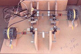
– 1st model 1992-09-06
the motor was barely strong enough
to spin these, smaller weights maybe
60 to 100 rpm and, they would not
spin the slightly longer, heavier,
weights at all. I also needed
stronger motors.
I traded them in for 1 hp 12 amp
motors but was reminded by a
friend that household wiring could
not handle 2 12 amp motors, so,
I traded them for smaller, lighter,
1/5th hp 10,000 rpm ele. motors
on 1992-09-21. Nothing rational
about that. – but, later, I found
that air motors worked better
anyway.
No one seriously interested in a new, cheap, source of propulsion, or, one with such acceleration that it could be used in space (?!), need question or dispute anything, just build it and find out for ourselves. How much can it cost to build a frame for some mounting blocks for the rods, get some rods, 2 motors – just strong enough to spin the weights (“eccentrics”) – and some right angle gears. …
The first problem: The 4th line of the key to the drawing says “L is the base plate to which the motors, gear boxes, and pillow blocks (not shown) are fastened.”
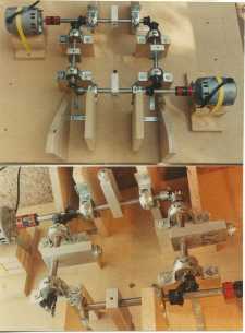
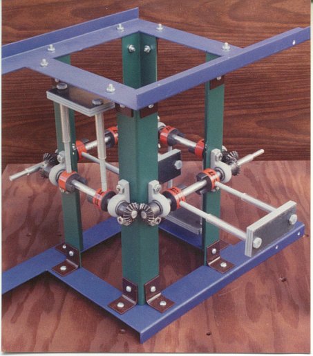
After building my first, wood, construction (Photos on the left and right) it became clear to me that building it “on” the frame was not quite enough because, on the next page, he says: “… there is a common point about which the center of mass of the eccentrics and the center of mass of the device as a whole gyrate.” (pg.32) Meaning: everything below the spinning weights must have its counterpart above the spinning weights as well. To be “centered” there must be both a top and a bottom plate for the rods and gears etc. to be mounted between. (see Feb. 1993 photo below)
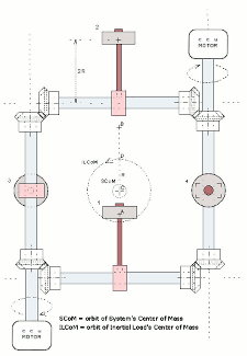
flying stove, blueprint : Fig.1
We need 4 vertical struts which we will place in a square arrangement to hold the top and bottom plates. The 4 rods, drive shafts, will be mounted around the center points of the 4 vertical struts with mitre gears (a.k.a. right angle gears) at the corners. Again, as shown on the original diagram, we will mount 2 motors out on 2 opposite sides – so that the center of mass remains at the center of the device as a whole.
2nd Tesla Flying Machine design
2nd “Tesla Space Drive”
Since nothing is said about weight being an issue, my second (all steel) frame was built to be rigid, not light-weight. I estimated the weight to be about 30 lbs plus about 15 lbs in motors, pillow blocks, steel drive shafts, etc.
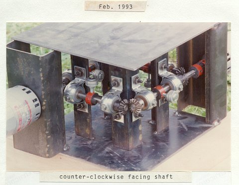
After spending almost $300 to have this iron frame built ($275 paid on 2-18-1993), I tested it. The new motors would spin the weights, washers on short bolts, but, one or two often came loose at start-up. The ele. motors accelerated them too fast. It was difficult to screw them on tight enough. When they were on tight enough and they did spin, the frame did not bounce around or even vibrate significantly but, it did not lift off either. I realized there must be some, higher, necessary speed to enable the device to move.
The motors can be anything you can get hold of. Your only requirement is that they be able to get your weights up to your needed speed. The book, does not mention a speed requirement (for the eccentrics) except to say:
[ It will ] wobble noticeably at low thrust (rpm) levels.
This effect fades out, however, as the thrust (rpm) is increased.
GENERAL NOTES
The 4 weights may not be the only loads on the system. If the 4 weights revolve fast enough, the air resistance becomes an additional overhung load. If the rpm of the weights is doubled, the radial load on the shafts is quadrupled (mass x radius x rpm x rpm x K = force).
Requirements of the
FORCE FIELD GENERATOR / MOTOR
This device converts inertial energy into centrifugal acceleration which, according to the right-hand rule, generates linear acceleration. The principal is the same for the way that the centrifugal acceleration of electrons, in a coil, exert linear acceleration on a metal rod placed in the center of the coil. Here, the acceleration is exerted on the frame. An electric motor is the result of electrons in orbit; this motor is the result of the center of gravity of entire atoms, the entire device, in orbit.
The rotation (rpm) necessary to generate acceleration depends upon:
- the mass of the entire device
- the mass of the 4 rotating inertial loads, (4 masses),
- the radius of those 4 loads (aka 4 eccentrics, 4 masses)
- and, the force of gravity
- For example, if the mass of the 4 inertial loads totals 1/10th the total mass of the entire device, then the radius of rotation of the center of mass of the system (the entire device) is 1/20th that of the radius of any one of the rotating loads. (not 1/10th. This is just geometry but, I overlooked it for a time) (only 2 of 4 weights going left to right and only 2 of 4 going front to back)
- It is the rotation of the entire system (device) that must get up enough centrifugal acceleration to defeat gravity.
- Examples of that acceleration are: On a 25 inch string (radius), something greater than 37 rpm ( experimentally 38+ rpm spinning)
This can be observed with a weight on a string. With a 25″ string, just swinging the weight back and forth like a pendulum, gives the same rate of oscillation with very little, almost no, arc as it does with significantly more – about 26.5 cycles per minute (cpm). Since there is no energy being applied to the pendulum and it will eventually come to a rest, it is intuitive that if there is any (constant) energy entered into the system to maintain spin, it will, be spinning at a rate greater than 26.5 rpm. In my continued experimenting, I found it took about 27 to 28 rpm to keep it spinning around, not just back and forth. With a 25″ radius, as a pendulum, there were 37 ocilations and, spinning, I had at least 38 rpm.
Feb. 1994: the frame is rigid and the motors are very light weight
With the lighter-weight air-motors, the total weight of this 4th model
generator is less than the previous one with its electric motors.
This system, as shown, should require only 1 or 2 hundred rpm but,
the motors were not strong enough to spin it at all.In March 1994, We tried it with 3, 2, and then only 1 crossbar. With 3 crossbars, 0. With 2 crossbars, it spun at maybe 60+ rpm. With only 1 crossbar, I think we got 200 to 300 rpm out of the motors. A friend said “Something is happening here.” It started shaking more, not less, when we reduced the weights (from 2 to 1 on each side) and got it spinning faster. Instead of shaking less, it did the opposite. Something was happening.

In 1992 when I read about this and saw the diagram (above) It was so simple and easy to build, there was no need to question or dispute anything, just build it and find out for ourselves. I did not anticipate that the “eccentrics” would have to spin so fast that it would be a problem. I would like to think that a person can simply build a smaller model requiring less spin and get results.

I read of how Tesla was financially ruined by J. P. Morgan to keep his A.C. motor and other inventions from reaching the public. I have read about so many inventors who have come up with things of great benefit to mankind who were tricked, threatened, financially ruined, or killed to keep their invention suppressed and maintain the financial well-being of those in power and I started www.fuel-efficient-vehicles.org.
Today, Brad Olsen (book: Future Esoteric) describes 12 different “UFO”s our military has built over the years. In a recently discovered manuscript of Tesla’s, he describes his confirmation of the ether and how he could use it to propel a space craft. … after describing the catastrophic explosion he created to prove the existence of the ether! (see our page “Tesla’s Unk. Manuscript” – and his Biography page, below)
My experimenting, continuing in 2006, is on the next page
Continued on Page 2;
the experiments, the notes
and visitors’ comments


