


updated 08-02-2014
from Tesla’s Flying Machine, page 1
Tesla’s Flying Machine
Page 2
“Tesla’s Flying Stove”
“Not the airplane, the flying machine,” responded Dr. Tesla.

A few weeks later, I traded these motors for 10,000 rpm 1/5hp motors.

Sept.12th, 1992
Second Tesla Space Drive Design
Since nothing is said about weight being an issue, my second
(all steel) frame was built to be rigid, not light-weight.

it was right after this that I figured out the speed
requirement and the variables that affect it
Third model, with 10,000 rpm ele. motors

The only expensive parts are the motors, (aluminum) pillow blocks, and mitre gears.
The pillow blocks, and mitre gears, combined, totalled $138.44. About a 2 foot square sheet of aluminum was less than $10. The shafts are also aluminum and cheap.
The shafts and pillow blocks are also, now, aluminum alloy. This model was fine but, the frame was just a little flimsy.

Note: I used the red/orange (Lovejoy) jaw couplings because they were a cheap easy way to attach weights on a shaft. I just replaced the set-screws with bolts. For a good close-up, click on the photo above (the 3 photos) to see an enlargement.
Experimenting out in the back yard, 1993

here I and a friend discovered the frame flexed a little

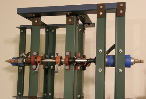
Final design: January 1994
using .090 inch aircraft aluminum ($9)
and 2 22,000rpm air motors ($50)

the frame is rigid and the motors are very light weight
I made the frame taller to accommodate longer arms and, slower speed requirements but, that was not necessary. However, there is an increased strength and reduced stress benefit to the double arms.
photographed on Fri., March 24th, 2006

Oct. 20th, 2007:
A few weeks ago +/- I tried it without any crossbars but, the weight and inertia were still too much for the motors. we got maybe 200 rpm but, we need maybe 600 to 800 rpm? I think the air pump where I am trying it, is not as strong as the one I used in Phoenix.
Nov. 2007:
I bought 2.5″ bolts and 1.5″ bolts so I have 2 more options. If the 2.5″ does not reduce the weight and inertia enough to enable the motors to get up some significant speed, I can try the 1.5″ bolts.
Cutting the length, and weight, in about half (from 4.75″ to 2.5″ bolts) reduces our net radius from about .1″ to about .025″ and our needed speed from about 600+ rpm to about 1200 rpm. Although it was an improvement, It just was not enough improvement and we switched to the 1.5 inchers. (see “December 2007” photo below) We started it up and the speed finally seemed significantly improved. A mechanic said it looked like it was going about 5 or 6,000 rpm. Great! Finally! Still, nothing more happened and we turned it off.
(we have no way of confirming how fast it was going – I think maybe only 1 or 2,000 rpm)
December 2007
Afterwards, I realized several potential problems. (1. The force may have been exerted downward instead of up (we need to try turning it upside down) and, (2. the 2 air hoses were adding weight to the system, holding it down. We need to prop the hoses up so that they do not add weight to the system.
Jan. 30th 2008:
We tried it again, right side up and upside down. We held up the 2 air hoses. But, no movement, no lift. It may be that we need 3-4000 rpm but are only getting 1 or 2000.
Testing at an auto body shop, Jan 30th 2008
 |
 |
June 30th 2008
If we got several thousand rpm, enough(?), then, it didn’t work. If not, then either a further reduction in the mass and inertia of the rotating weights and / or a change to stronger motors is needed.
Hopefully, we can get a sufficient speed increase by further reducing the weights & inertia. If not that, then by getting the weight of the motors off the frame by using couplers to extend the 2 shafts out beyond the frame.
March, 2009
I started getting calls from a TV production co. in Calif. wanting to put my flying machine on a Discovery Channel special.
I stopped at the auto shop, told them about it. They told me that they have gotten a new, stronger, compressor. Now is the time to try again!
Saturday, March 21st, 2009
Saturday was a disappointment. The new compressor provided significantly more power than the old one. The speed was much improved, very impressive, “more than enough”. This time I do think it was up to 3 or 4000 rpm, if not more. However, the weather was bad, raining, and I only did half the test. Still, it did not move. There was plenty of speed in the rotating masses. So, either I had it upside down, 50-50 chance of that being true, since it is totally symmetrical, or there is some stumbling block, some criteria I have not thought of.
Wednesday, July 22nd, 2009, 9am
Tried it again. The speed, again, seemed enough. But, again, I can’t be sure, and it did not go up.

2011, Footnote:
A frame is cheap, a person can design and build one around motors they come up with, the smaller the better, perhaps. Smaller motors can generally run at higher speeds. Extension rods, longer rods, can be used to get the motors off the system, and that will reduce the total weight greatly.
Here is one Marcelo B. built. Glad to hear from him.
back to Tesla’s Flying Machine, page 1
Hi guys, you did a real good job gathering together on this subject, (sorry for my spelling in english). I just want to tell you that this machine really torment me from few years (when i first time hear about it) and i almost twist my brains out in the strugle to find out how it works … and here i’m in this lucky night ..finding your site and having some revelations.
Ok, coming back to the subject, if i understood well there are some important things to be pointed out:
1) the whole table with everythings on it should gyrate(otherwise no “effect” occur)
2) this “compartementalising” of the design in 4 parts it seems pretty peculiar for me because after reading the comments that visitors have made it (especialy a particular one) i had a revelation-the comment was about introducing magnets instead of just mecanical eccentric masses-because i read in the last years internet literature about montauk and stuff but this design remembers me of well known “delta T antenna” which was a pretty similar device, but instead mechanical drive forces the last one have been powered purely electricaly.
3) other resemblance that stroke me was that it could be compared with a “tetra polar magnet” by it’s way of functioning. (this term is extracted from occult /alchemy terminology…see Franz Bardon)
4) it remembers me some explanations about philadelphia experiment wich involve Einstein in that experiment triyng to solve his U.F.T. (unified field theory).the theory of the theory stipulates that electromagnetic field was “geometrized”, which exactly means planes separation of forces x,y,z, (via 3 coils-shaped as an octahedron each plane from x,y,z, has a driving force).
Actually in the “Montauk” literature this device has other purpose than fliyng, was a kind of time witness, for the entire philadelphia exp. time witness meaning a perfect time 0 generator,wich brings back the whole ship in the time that it belonged (1943) not elswhere or in random time spaces dimensions.
Maybe you will tell me that i`m dreaming, while you (guys) are concerned with precise /matemathical/mechanical , calculations about this machine…but don`t forget, the Tesla himself was a dreamer also (read biography), and a weird person too.
hope you find interesting my “associations”, bye.
Adrian
by the way, Tesla was involved in the Philadelphia experiment till he realized it was dangerous, people would get hurt, and dropped out.